I’ve spent the last 15 years (or so) in the software world. With a new software project you have nearly endless flexibility and can be pretty loose with your plans. With hardware, you’re much more constrained. There are limits on features, integration points, and the physics of moving electricity around. So before starting to build, I needed a plan.
Component selection
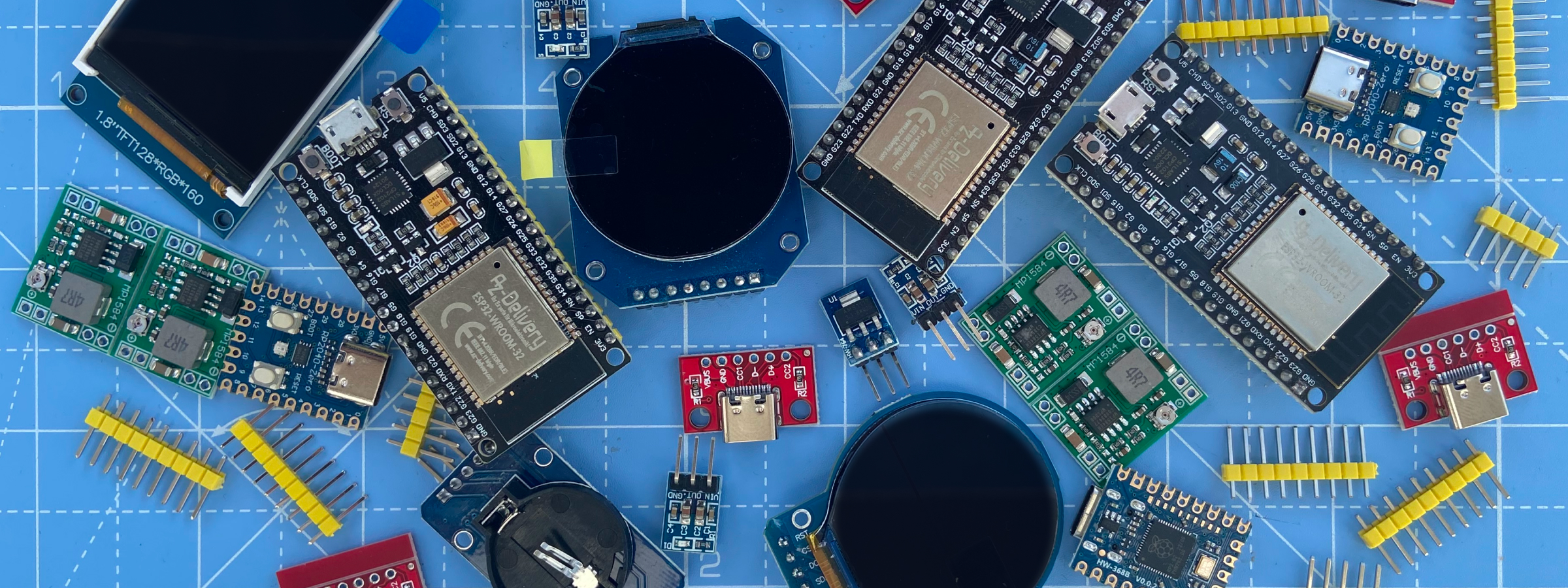
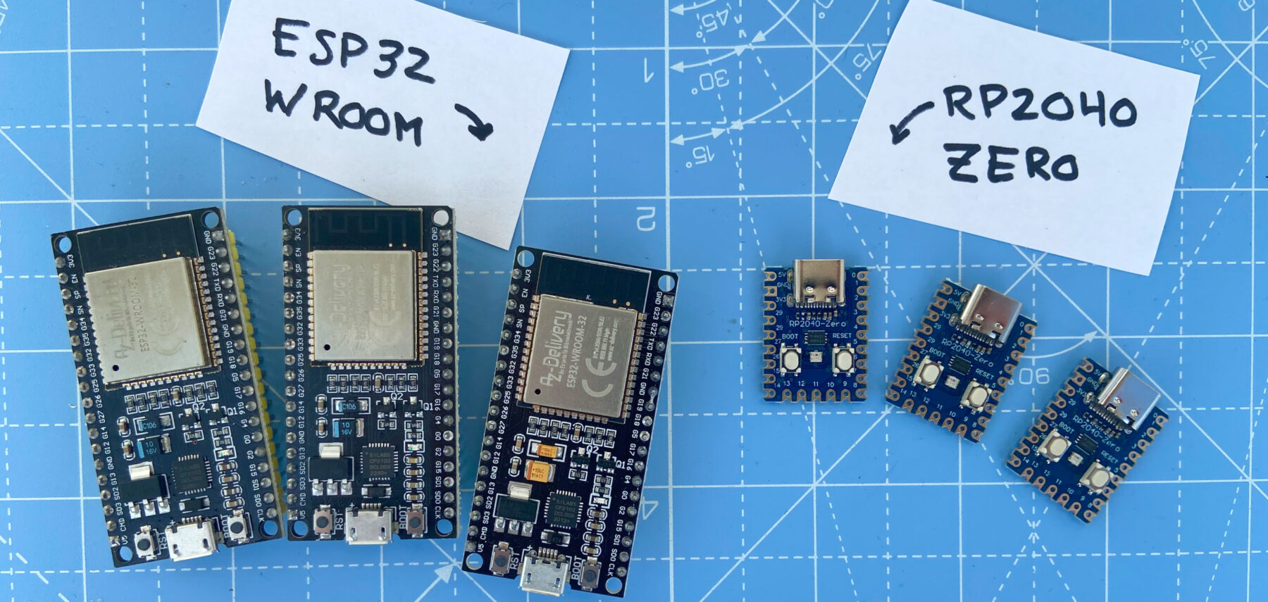
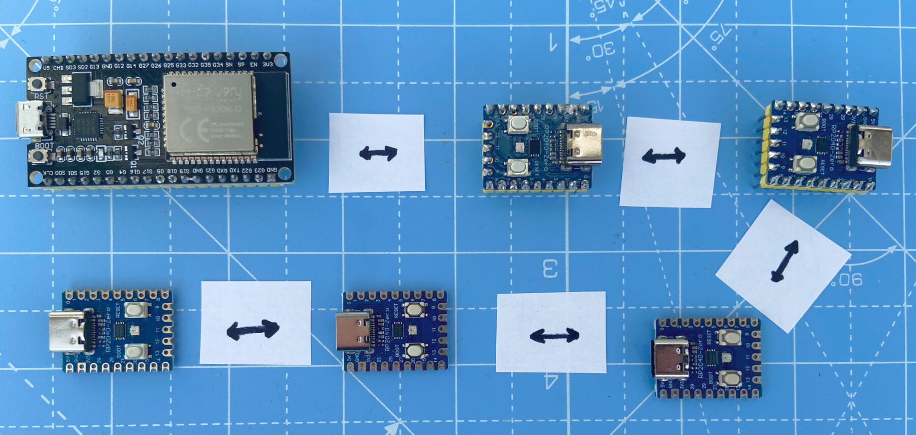
I started with component selection. I knew I wanted a hub and module model, with the hub providing the brains and power. ESP32 seemed like the default choice. Development boards are reliable and cheap, with a variety of form-factors, and nearly endless resources.
For the modules, I was less certain. I wanted something small, with a decent amount of power, is affordable, and had a good SDK and community. My search led me to the RP2040-Zero, a dev board built around the RP2040, Raspberry Pi’s popular dual-core microcontroller. This seemed like a solid choice.
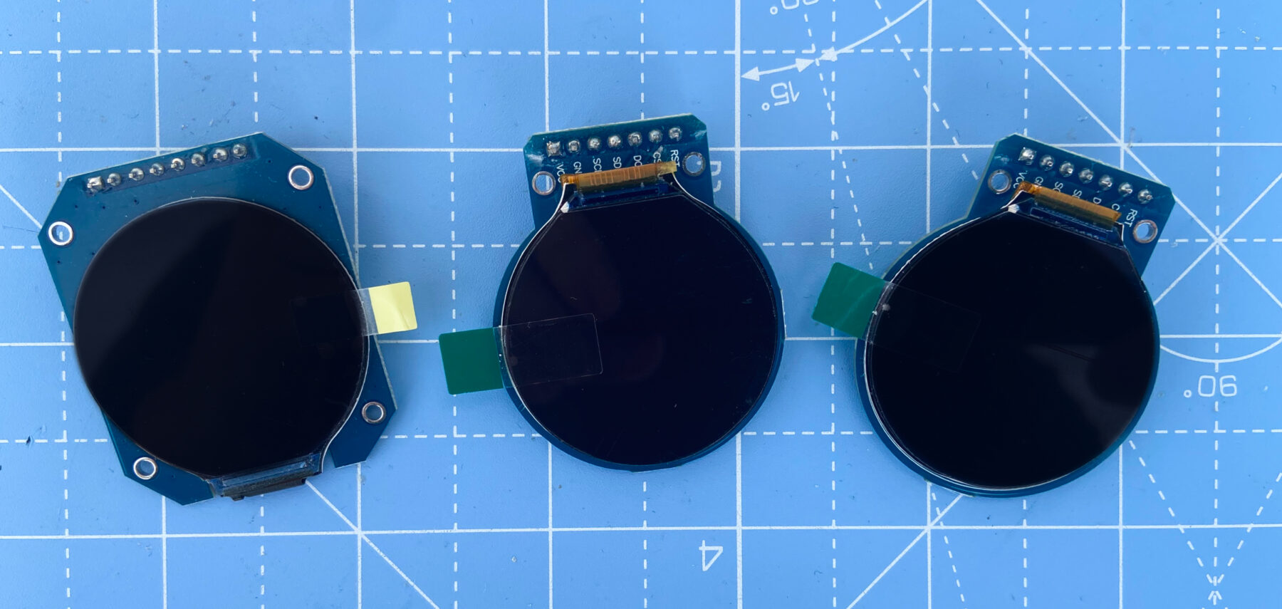
For the screen module, I wanted a round display for a more organic, less rigid feel. I also wanted something small, with good resolution, and not overly expensive. I landed on the GC9A01, a 1.28-inch, 240×240 pixel screen. After using it, I’ve been impressed with its brightness, visual clarity, and ease-of-use.
There are more components to finalize as the design matures. For example, I need to figure out power delivery, which will most likely use a USB-C breakout board and various protection layers. I’m also searching for higher-end switches and dials to meet my quality target.
Physical architecture
Another major set of decisions were how the hub and modules would be arranged and communicate. I debated between two models: hub-and-spoke and daisy-chained.
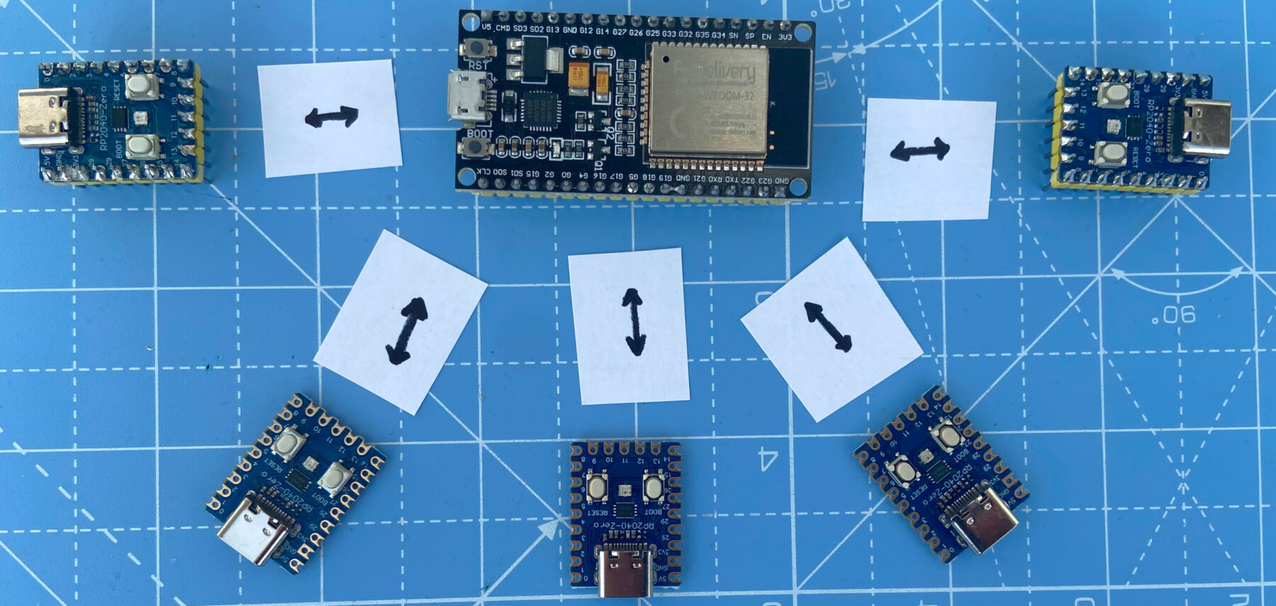
A hub-and-spoke approach seemed easiest to engineer. Each module would connect directly to the hub, so no congested communication channels or routing complexity. However, this approach is limited by the small number of communication channels available on dev boards. It also means more and longer wires in the panel.
A daisy-chained approach could be messier, with multiple messages across the same communication channel and more complex software to handle addressing and message routing. But the wiring would be cleaner and I could potentially chain more modules on a single hub.
I choose the daisy-chained approach for its clean hardware and flexible software.
Communication method
I also needed to decide the communication method. There are several options, most prominently UART and I2C.
Each method had pros and cons. I liked how I2C provided built-in device addressing and simple wiring. However, it doesn’t support sending and receiving simultaneously (full duplex) and is typically limited to low speeds and short messages. In contrast, UART supports full duplex, is faster, and supports larger messages. While UART lacks built-in addressing, this can be handled in software.
The pros of UART better suited my intentions, so that’s what I selected.
Choosing UART did highlight an earlier mistake. I had several ESP32-WROOM boards on hand, so I started with one of these. Unfortunately, while the WROOM model does have three UART controllers, two are used by internal systems (programming/debugging and flash communication), leaving just one for module communication. I’ll replace the WROOM with an S3, which has two free UARTs and the added benefit of a faster processor.
Next steps
With components chosen and a plan in place, it was time to prototype. I grabbed my development boards, breadboards, and wires and got to work.
Comments
This post has no comments.