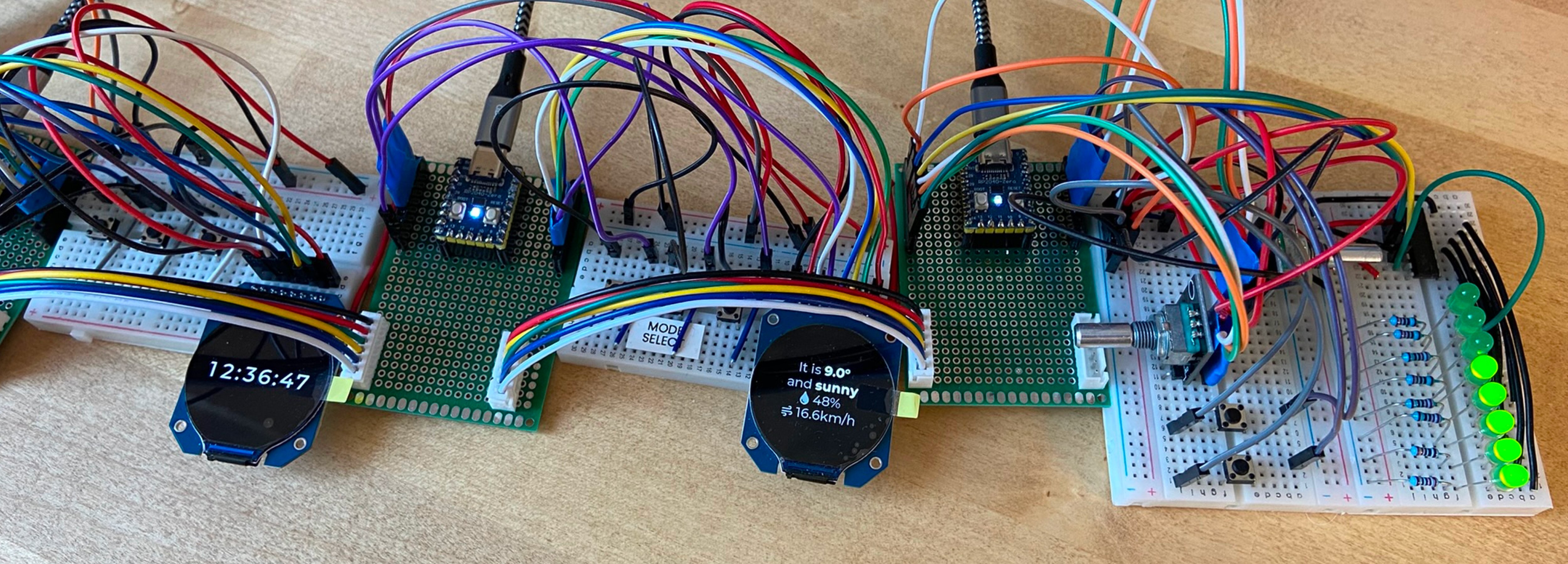
WeavePanel just reached a major milestone: a working proof-of-concept.
It shows live weather, reliability controls lights, keeps the time, and more. There’s a lot of work before a proper prototype, one that I can put on my night table or send to early testers, but it’s solid progress.
If you’re interested in testing, sign up for the newsletter. I’m hoping to send early prototypes in the next few months.
First tests
To see how I got here, let’s go back to the first connected wire and written code.
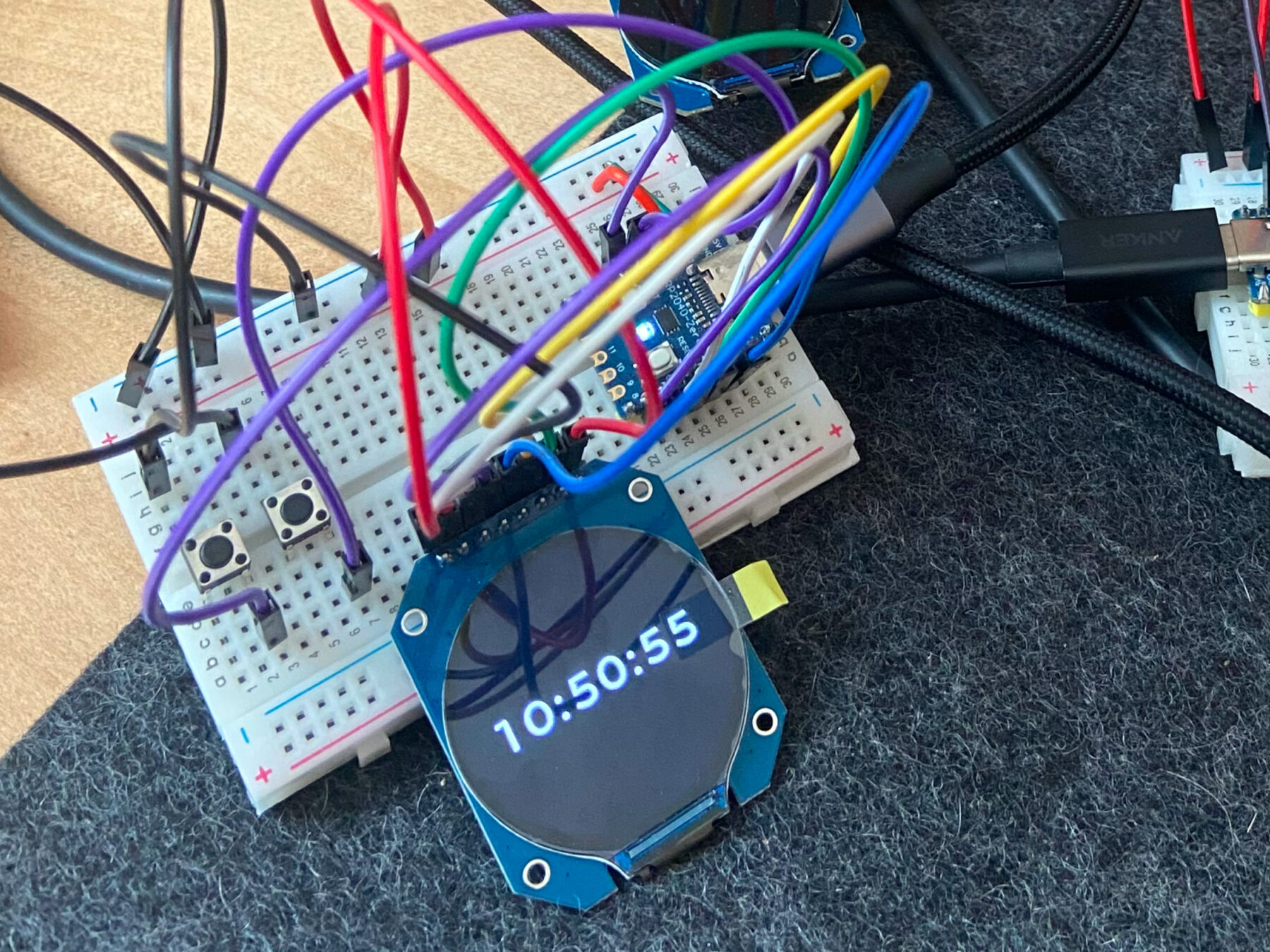
After much planning, I started wiring components on breadboards (a way to wire electronics without soldering). I started with the screens, because they look the coolest. I defined pin-outs and wiring, then tested some code. Next came the buttons and dials.
Once I had each component working independently, I moved to one of the biggest challenges: communicating between modules. After much trial and error, with both wires and code, I successfully sent a few bytes of data down the chain of modules.
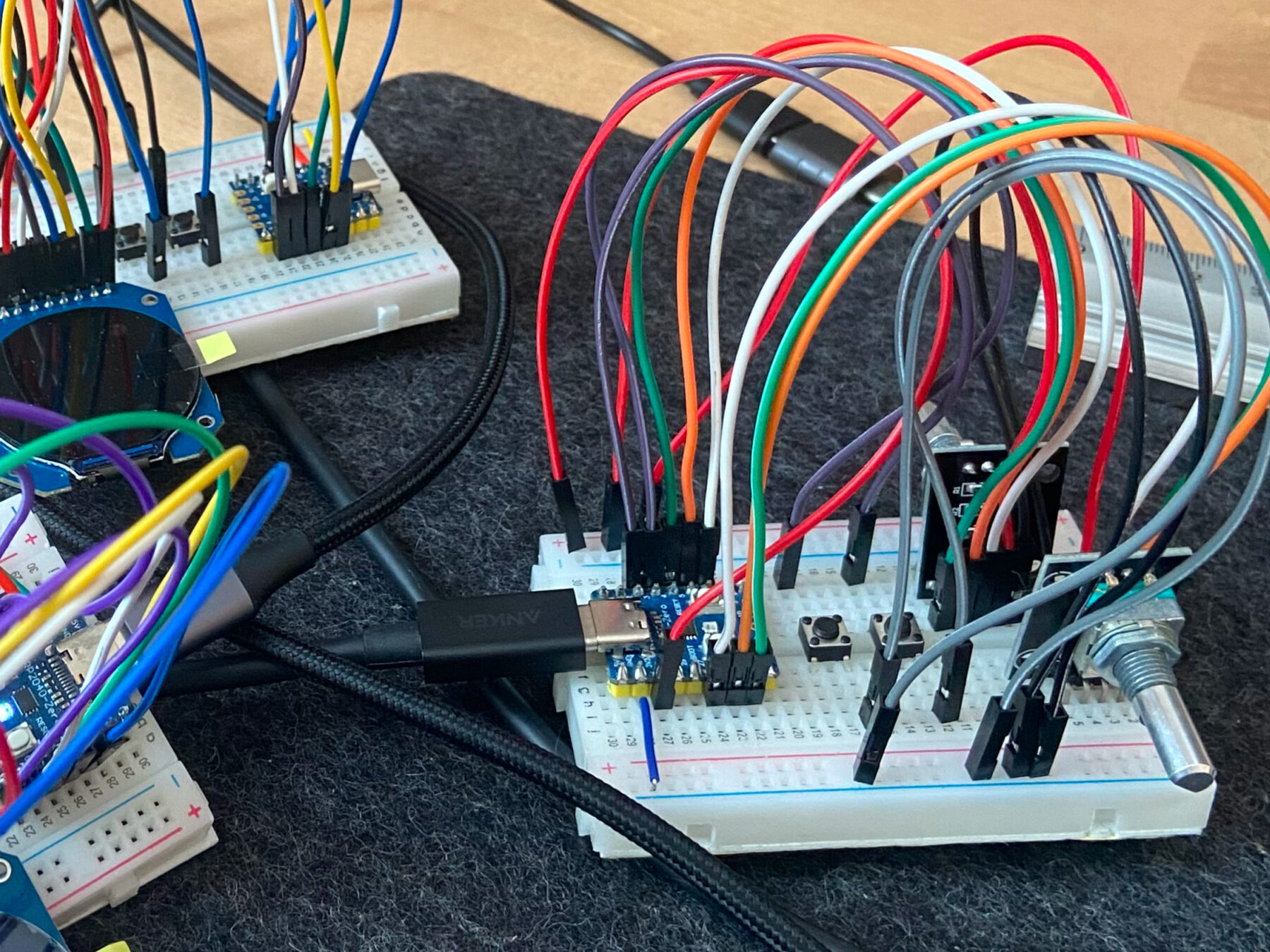
This was a start, but a few bytes wasn’t enough. A module might need a weather forecast or a light’s detailed status. Longer messages usually made the first module-to-module hop. Unfortunately, the second hop caused nicely formatted messages to became a corrupted mess.
More tinkering and research led me to a single conclusion: breadboards were too electrically “noisy” for clear communication. I needed clean wiring, and that meant soldering.
Soldering
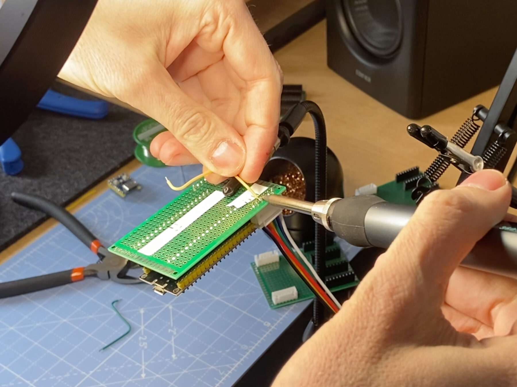
I was not looking forward to this step. I knew soldering would be necessary, but I’d only done it once before, and that was a minor disaster.
Undoing a soldered joint is a lot more involved than pulling a wire from a breadboard, so I didn’t jump right in. Instead, I made a plan.
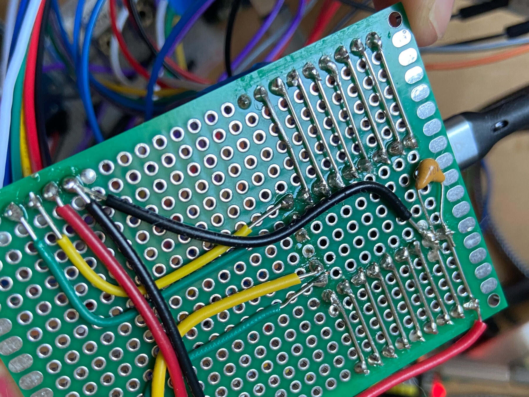
| Drafting wiring designs I wanted to minimize the potential for mistakes, so I created color-coded, high-resolution wiring mock-ups in Figma. I referenced these while soldering, which made it much easier to know which wire goes where. I also added color-coded labels to the perfboards to make sure I didn’t mix up my RX, TX, power, and ground lines. | 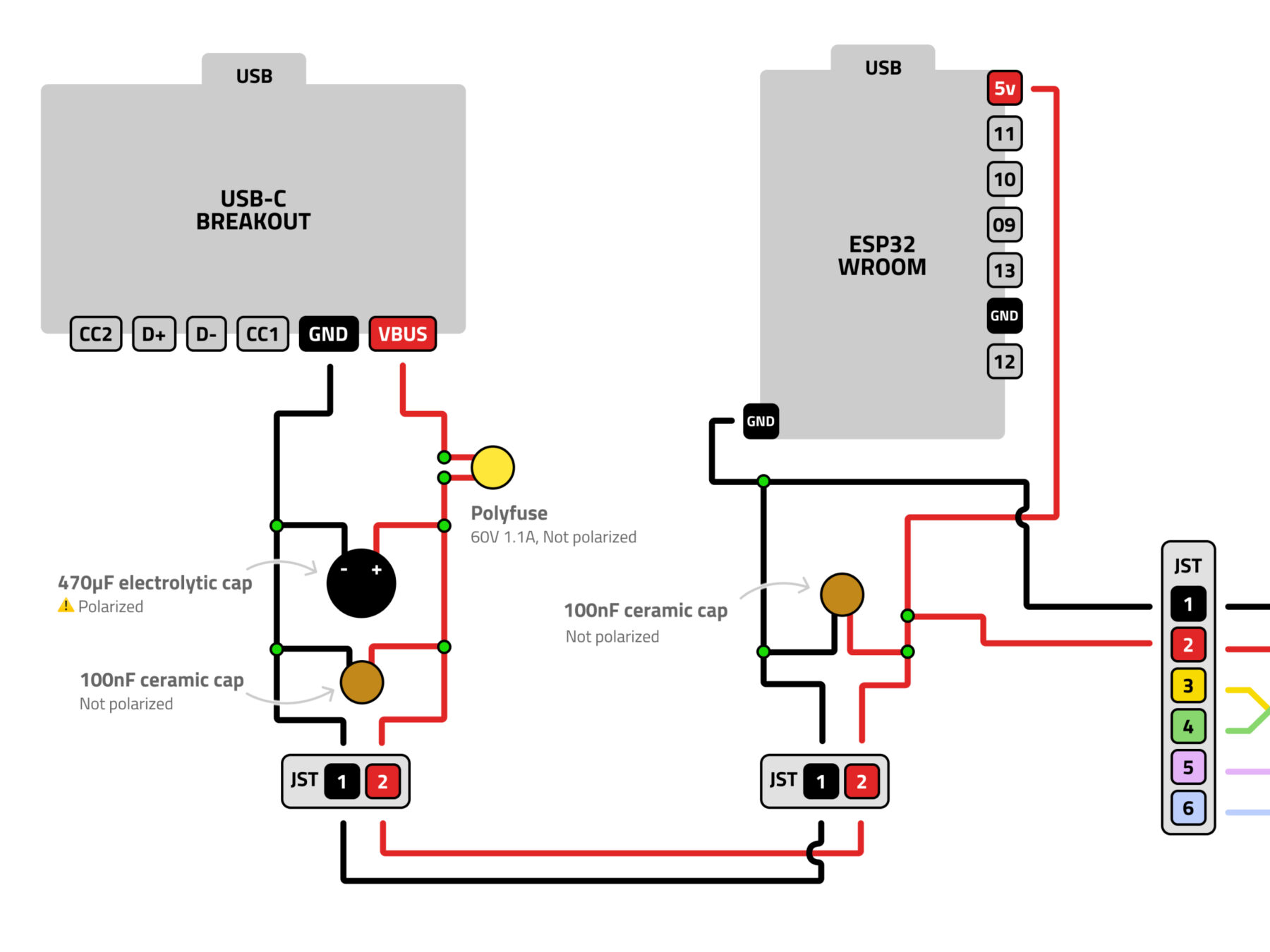 |
| Adding supplemental headers I was still figuring out components and wiring, so I didn’t want to solder everything. I only needed clean UART RX, TX, power and ground wires, so I wired every other pin on the microcontrollers to a external headers. This way I could still use flexible breadboards for less sensitive parts. The microcontrollers use the headers, so they are also removable. | 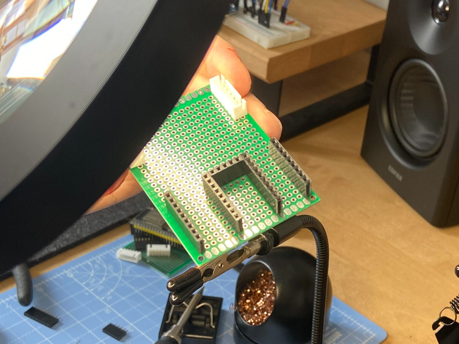 |
This was my first time using a multimeter. It proved a life-saver. Being able to check electrical continuity made diagnosing and fixing poor connections dramatically easier. Hearing a final confirmation beep when testing an end-to-end chain was enormously gratifying.
After much effort (and a little swearing), I had UART communication lines and power rails wired up, tested, and ready for code.
Coding
This phase proceeded more smoothly. I also had the help of Claude, which is pretty good with code (but useless at soldering). I’m working to balance my use of LLMs since I view them as a risky dependency.
There were a few areas where LLMs were particularly helpful though.
Supplemental tooling
WeavePanel uses self-contained modules, each with their own serial debug channel. However, most monitoring software only shows one channel at a time, so I was constantly switching between windows to see the full WeavePanel network.
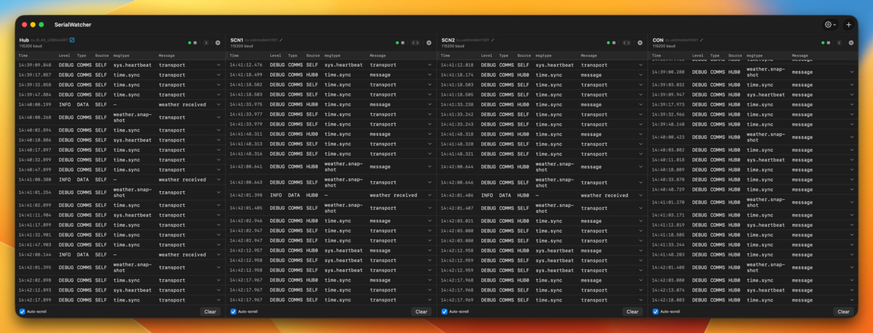
I wanted to see every output on a single screen, but I couldn’t find a suitable app. So, with Xcode and Claude, I built a custom Mac app. Since this is internal tooling, making me less picky on design and code quality, I was able to hack it together in a few hours. This custom tool immediately helped identify and fix a timing collision that had been plaguing my communication channel.
Build scripts
Another challenge with multiple modules is they each have their own set of code. Claude was able to put together custom build scripts and PlatformIO environments. I could have every module plugged into a USB-C hub, and then use scripts to define which module should get which code. Having to unplug one module and plug in another just to upload some code was annoying, so these scripts were a welcome addition to my workflow.
Communications library
Of course, rosy LLM stories need to be balanced with some reality. The first version of the communication library, coded by Claude with minimal oversight, was quick and dirty. It worked, barely. It was also over-built, inconsistent, and confusing.
I almost immediately started redesigning it. For the second version, I gave Claude a more detailed prompt, but the result was still excessive and buggy.
For my third try, I set aside time to do it right. I wrote a detailed protocol structure before jumping into code. I did use an LLM to validate my thinking, brainstorm better terminology, and catch anything I missed. This third version, which was still partly LLM coded, is dramatically simpler, and much easier to monitor and debug.
First heartbeat
With the hardware wired and code in place, I was beginning to see the weeks of work paying off.
- I was pulling real-time weather from Home Assistant and seeing it on a screen module.
- I could turn a dial and see a light brighten or dim. I found this so exciting that I made my wife drop what she was doing and watch me turn on a light.
- I also added a real-time clock module, so the clock keeps perfect time through reboots.
At this point, I started imagining how to pull everything together into a single box for a real prototype.
A big problem, or how constraints can create something cool
I did run into a significant, possibly unsolvable, problem.
I want a dimmer on my panel. Typically, this is implemented with a rotary encoder, which sends electrical pulses as it is turned. These pulses can be converted into commands to increase or decrease a light’s brightness.
Unfortunately, there are two problems with this approach:
- There are a lot of pulses, and they can get bunched together or completely dropped. The result? A light that stutters and jumps when dimming.
- Each command has many hops between the dial and light, often multiple WiFi connections, hubs, routers, through walls, and more. Each hop takes time and reduces reliability, making the light change even messier.
But I had an idea. Some existing products with dials dials incorporate LEDs to show the selected level. Here are a couple examples:

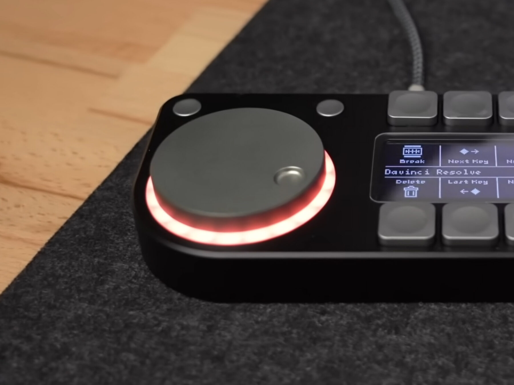
The LEDs provide immediate feedback, so a short delay in changing the light’s brightness isn’t as noticeable. It also means the module sends just one command with the amount of change, rather than many smaller messages. Less messy and more reliable. Plus, it just looks cool.
What’s next
From the initial idea and sketches, WeavePanel is now a functional system that tells weather, controls lights, and keeps time. There’s still a lot to do, including rewriting most of the code, building a proper enclosure, and real-world testing, but it is starting to show its promise.
If you want to follow along, or be considered for an early prototype, sign up for the newsletter. I hope you join me on this adventure!
Comments
This post has no comments.